 Mr. Chen:136-6225-2835
 Miss Chen:189-2385-0895
Shenzhen Guangjiayuan Electronic Technology Co., Ltd
Mr. Chen: 136-6225-2835 (same WeChat account)
QQ: 979285705
Miss Chen: 189-2385-0895 (same WeChat account)
QQ: 2391552662
Chen Weiting :135-3824-4786 (same WeChat account)
Chen Weihao: 139-2459-4393 (same WeChat account)
Tel: 86-0755-33182327
Email: gjydz88@163.com
Website: www.usb-type.com
Address: Building 10, Hongxing Gebu Qixiang, Songgang Town, Bao'an District, Shenzhen, Guangdong Province
In the past, many friends have suggested that our new boards be replaced with USB type C (referred to as USB C), and I personally believe that USB C will soon replace the original mini USB and micro USB as the most common connector for communication and power supply because of its reversibility, 100W power, and 20 Gbps data transmission. I just feel that there are too many micro USB cables in everyone's hands, and adding another USB-C cable is not environmentally friendly, so I still used a micro USB connector.
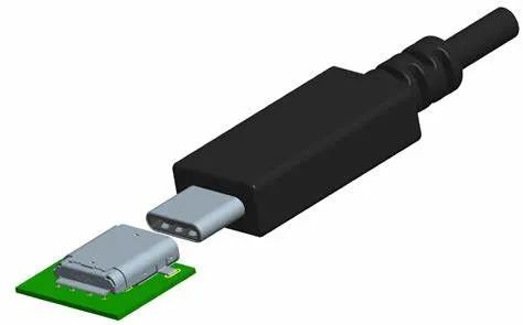
The trend still needs to be respected, and one day it will need to be changed. So, starting from now on, all new board designs will use USB C. Switching to C requires understanding the differences between C and the original mini and micro. Therefore, Teacher Su spent the weekend reading a popular science article (divided into three parts) about USB C. Although it was from 2016 to 2017, it felt very easy to understand, I have also shared its main content here.
The following is the main information of the article:
The article first reviews several concepts that are easily confused with C:
usb 3.1
usb SuperSpeed和SuperSpeedPlus
usb type c
usb Power Delivery 2.0
usb 3.1
USB 3.1 is a specification released by the USB implementers forum, which is the overall standard for next-generation USB devices and cables. It includes everything you need to know to connect to the latest USB hosts and devices.
USB 3.1 version 1.0
usb type c Rev 1.2Or higher version
usb Power Delivery Rev 2.0Or higher version
USB port controller version 1.0 or higher
usb SuperSpeedPlus
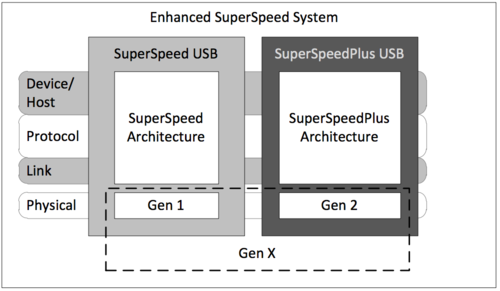
USB SuperSpeedPlus refers to the latest USB data bus with a running speed of 10Gbps/channel. SuperSpeedPlus emphasizes new features beyond SuperSpeed (not Plus). USB 3.1 uses "Enhanced SuperSpeed" as a general term to refer to the common functionality of both. SuperSpeed, also known as USB 3.1 Gen1, mainly refers to the physical layer.
The blue type A plug you see in the figure below has added five wires to support the new USB 3.1 bus. Both sending and receiving have a pair of differential pairs, supporting full duplex and additional ground.

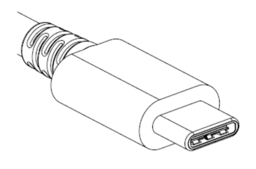
USB type c is the connector itself. The name comes from USB 2.0 connectors of type a (host side) and various forms of type b (device side), including standard B, mini B, and micro B. Using USB type C, it is not possible to distinguish the roles of power and data based on physical connectors. Both the device and host (source and receiver) will have USB C sockets, and both ends of the USB C cable will have the same plug, which is symmetrical.
This specification includes mechanical, electrical, and some functional details on how to use it. Some of these features include signaling data and power roles, available power, and whether the device is an attachment. The USB port controller specification provides a universal interface for ICs directly connected to ports. The purpose of this specification is to simplify software development.
usb Power Delivery(USB powered)
USB Power Delivery is where most revolutionary features are located. The term 'Power Delivery' is a bit inappropriate because its purpose goes beyond that. This specification describes how to exchange data roles, exchange power roles, move Vbus to different voltages, and how to use pins on USB C connectors for other purposes such as DisplayPort. This way, you can plug your laptop into the monitor to present the slides while charging and running the complete USB 2.0 hub, all with just one cable.
Let's focus on the USB type c interface of the connector, which is slightly larger than the micro-B interface. It has 24 pins in a radially symmetrical pin arrangement, making its direction reversible. Unlike previous versions of USB connectors, there are no physical differences in the plug, depending on the port or the functionality supported by the plug. USB C can complete all tasks.
The type c specification is a part of the USB 3.1 specification, as described in Part 1. You can download the complete USB 3.1 specification from USB. org. Follow the type c specification version 1.2 in the USB type c folder.
The pin arrangement is clearly symmetrical around the center as shown in the figure below.

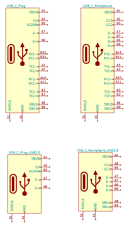
The following table shows the pin definitions for USB C sockets:
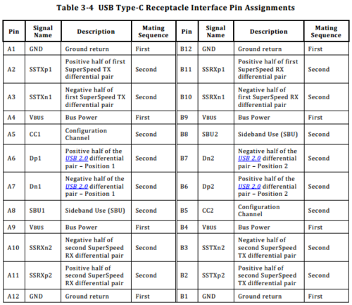
VBUS - supplying power to the load
DP (D+)/DM (D -) - USB 2.0 communication, supporting 480Mbps high-speed USB
SSTX1/2, SSRX1/2- Ultra high speed transmission, differential pair, usually twisted pair in cables
CC - Configuration channel for configuring connections and sending Power Delivery messages
VCONN - Connector power supply for active cables and accessories
SBU sideband is basically a backup wire used in backup mode
Points to note:
Interchange of SuperSpeed Tx and Rx lines in cables. The same applies to SBU wires. This means that the SSTX1 on one side is connected to the SSRX1 on the other side. Similarly, SBU1 is connected to SBU2 on the other side. You cannot use a multiplexer to solve this problem.
The differential pair has a differential impedance of 90 ohms. If you are using alternative mode, please ensure that it can handle 90 ohms+/-5 ohms
Cables can be electronically labeled. This means that one of the plugs has an internal microcontroller connected to the CC cable, which is responsible for reporting the functionality of the cable. All USB fully functional type C cables should be electronically labeled. Cables that only support USB 2.0 do not need to be labeled.
Pay attention to the power outage of devices hanging on VBUS. Using USB Power Delivery 2.0, VBUS can reach up to 20V, ensuring that this does not violate the rated voltage in the circuit.
Also be careful when supplying power from VCONN. You may not have. Alternatively, you may have to provide it.
One major advantage of MUXS USB c is its support for forward and reverse cable insertion, as shown in the following figure:
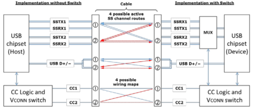
Determine the cable connection method by using CC cables. The wire is always in the same position on the plug and can only be connected to one of the two pins in the socket. The position opposite CC in the plug is VCONN. This is why plugs have CC and VCONN, while sockets have CC1 and CC2.

The configuration channel is used to determine the direction of the plug, the role of the communication device, the power function, and send the Power Delivery message. It is realized through the Pull-up resistor (Rp) and pull-down resistance (Rd) on the circuit.
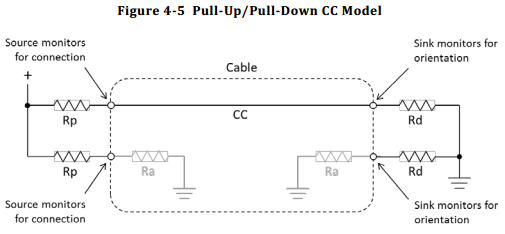
Even if the current of USB C does not support USB Power Delivery, it can still obtain up to 15W of power through the USB connector. VBUS is still limited to 5 volts, but the current may reach up to 3 amperes, which is achieved through an analog signal of the voltage on the CC line. Essentially, the signal source will change the value of Rp Pull-up resistor to set the voltage of CC line within a specific range.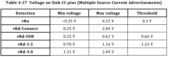
Using USB 2.0 design on USB C to support type C through existing USB 2.0 designs is both simple and inexpensive (except for connectors). Basically, you connect DP pins together, DM pins together, and then add a pull-down resistor on each CC pin. This new type C device will be recognized as data and power, using the default USB 2.0 power supply of 500 mA, and can operate in any direction of the plug.
There are many types of USB C connectors available in the market, with similarities and differences. Here are some key points to consider when selecting connectors:
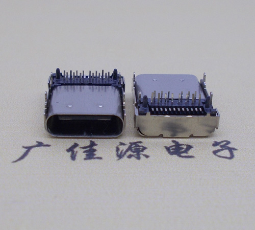
USB 2.0 vs. USB 3.0 vs. USB 3.1- Typically, type C connectors are designed for maximum rated transmission rate. USB 3.1 supports up to 10Gbps on DP/DM pins, USB 3.0 can reach 5Gbps, and USB 2.0 can reach 480 Mbps. Therefore, USB2.0 may not require very good shielding.
Right angle and vertical installation dual SMT or hybrid - some connectors have two rows of 12 SMT pads per row. The hybrid connector has an outer row of SMT pads and an inner row of through hole pins. Note that through hole pins are typically designed for PCBs with a thickness of 0.6-1.0 mm.
The days of relying on USB connectors to support the required current and voltage ratings are gone. If you need a voltage greater than 3.0 amperes or 5.0 volts, please carefully check the current and voltage ratings.
The article also includes pictures of the technical articles read:
Source: FPGA Beginner to
Proficienthttp://www.gjytype.cn/news/xydt/2020/0827/905.html
Contact person:
Mr. Chen 136-6225-2835 (same WeChat account)
Miss Chen 189-2385-0895 (same WeChat account)
Chen Weiting 135-3824-4786 (same WeChat account)
Chen Weihao 139-2459-4393 (same WeChat account)
Address:
Building 10, Hongxing Gebu Qixiang, Songgang Town, Bao'an District, Shenzhen, Guangdong Province
 |
 |
| Technology 1 | Technology 2 |